In previous section, we studied different types of Stepper Motor and Lead identification of Unipolar which is commonly used. These parameters user must understand before interfacing with Micro controller
Technical Parameters:
· Motor Speed
· Holding Torque
· Step angle
· Step per second and rpm relation
Motor Speed
The motor speed, measured in steps per second (Steps/s), is function of switching rate.By Changing the length of the time in Delay, we can achieve various rotation speed.
HOLDING TORQUE
Holding torque is defined as the motor shaft at stand still or zero rpm condition, the amount of torque from external source required to break away the shaft from holding position.
STEP ANGLE
The step angle of any Stepper Motor depends on the internal construction of the motor, in particular the number of on the stator and rotor. The step angle is minimum degree of rotation dealt with a single step.
STEP PER SECOND AND RPM RELATION
Steps per second = rpm * steps per revolution
60
STEPPER MOTOR RATING AND SPECIFICATION
Stepper motors nameplates typically give only the winding current and occasionally the voltage and winding resistance. The rated voltage will produce the rated winding current at DC: but this is mostly a meaningless rating, as all modern drivers are current limiting and the drive voltages greatly exceed the motor rated voltage.
A stepper's low speed torque will vary directly with current. How quickly the torque falls off at faster speeds depends on the winding inductance and the drive circuitry it is attached to, especially the driving voltage.Steppers should be sized according to published torque curve, which is specified by the manufacturer at particular drive voltages and/or using their own drive circuitry. It is not guaranteed that you will achieve the same performance given different drive circuitry, so the pair should be chosen with great care.
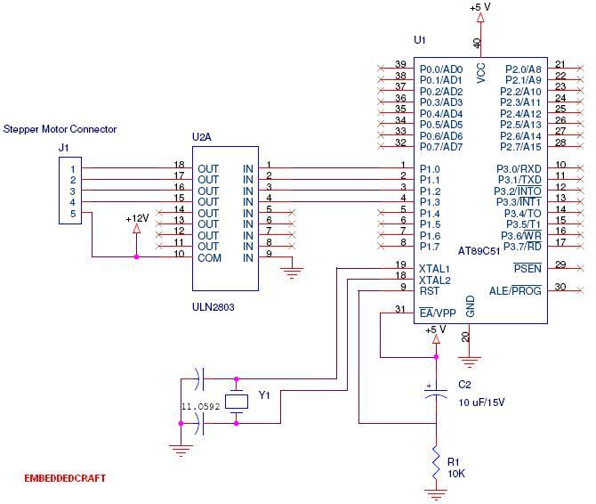
INTERFACING 8051 WITH STEPPER MOTOR
One Phase on Sequence.
In this, we are interfacing stepper Motor with One Phase on Sequence. In one phase mode, each successive coil is energized in turn. One phase mode produces smooth rotation and lowest power consumption of three modes. Steps are applied in order from one to four. After step four, the sequenced is repeated to step one.
The Stepper Motor is easily interfaced with 8051 and ULN 2803.Darlinton pair with high current rating. User can make Driver Circuit with help of Transistor. But IC’s ULN 2803 is best method for ease of design. User can use Pull up and Pull down for enhancing or decaying the value of current.
CODE
$mod51
ORG 00H
MOV A, #88H ; 10001000B
LOOP:
MOV P1, A
ACALL DELAY
RR A ; ROTATE BITS
SJMP LOOP
DELAY:
MOV TMOD, #01H
MOV TCON, #00H
MOV TL1, #0E0H
MOV TH0, #0B1H
SETB TR0
WAIT: JNB TF0, WAIT
RET
END